I am officially now trying to get ubuntu on this. After 3 attempts of a working recovery connection and getting error 0x80070002 each time I am moving on.
I have made the connections to J23 and placed a permanent mini-USB port on the back.
TTL-to-USB adapter stuck to rear of display cover with double-sided tape
With this, I was able to now see the BIOS screen and I followed these videos to start my install, but I want to store the OS directly on the drives so I am currently trying my first install right now. I will post back when I get further along.
I recommend that you install the OS to a separate 5th SATA drive, rather than the drives that are part of the Raid array.
The pads for the connector for the 5th drive are right there in the left rear corner of the board viewed from the front of the unit. It’s a bit tricky, but you can install a SATA connector there and connect up to a 2.5" SATA SSD that you can mount along the side next to the main 3.5" drives. Then you just need to locate +5V to power the drive.
This is the preferred topology for a Raid 5 system. Make a backup (not on the Raid) of the boot drive. Anything goes wrong with the boot drive, data is safe on the main Raid array. Just replace the boot drive and restore the backup boot image.
Yes, that’s the one. It’s easiest to use a right-angle SATA cable so that the cable angles downward. I mounted a 2.5" SATA SSD on the other side of the enclosure in the open area on the side. Then I ran a small cable from the +5V available on J2 next to the dimm memory connector.
Great… I found your other post on all the other connectors. With all this info I am totally moving this a Linux box. I have been playing around with lcdproc to get the lcd to display information but I have some more work to do on that front. The documentation on it is not the best for a non programmer. But I will get there. Working with the default customized OS is finicky and with MS removing hot fixes from their servers makes it even harder. For what I intend to use this box for I think this will be my best path.
Ordered the SATA connector, and a pin header for the VGA, a small ssd and by end of next week I should have a much more user friendly box. Especially if I get the VGA working.
I already have upgraded the ram to 4gb. So after this not much else will have to be done. With the OS on the SSD and the drives as raid 5 should be a nice box for a me.
The LCD is connected to the SuperIO chip, specs for which are available online. It is using the Hitachi LCD protocol. Pretty straight forward. The SuperIO chip also runs the cooling fan under purely OS software control. That is, the bios does absolutely nothing to control the CPU and drive temperatures. The fan just runs at max speed until an OS driver takes over. The fan is connected to the SuperIO SysFan control pin. There are several more fan outputs on the SuperIO that are not used. Ideally, software should monitor both the CPU temp and the drive temps via SMART cmds and control the fan speed appropriately.
The VGA output is pretty murky looking, but infinitely more serviceable than trying to install an OS the WD way.
There are PS/2 mouse and keyboard ports on the SuperIO and I have hooked them up, but it stretched my rework/soldering skills way past being worth it. If you hook up the two extra USB2 ports, you can connect the mouse and keyboard there. It’s way easier than trying to get the PS/2 ports working. Otherwise you’re always fighting with not having enough ports for USB stick, USB mouse and USB keyboard. Not as critical for a Linux install, but really frustrating for any GUI install.
As for software vs hardware RAID, the distinction is a bit subtle. It mostly has to do with what else besides reading/writing the individual RAID drives, the CPU is doing. If you setup the DX4000 with no additional loads beyond the RAID itself, I would argue that IS a hardware RAID. It’s when you start loading down the CPU with a bunch of other stuff (ie Plex server, transcoding, torrent client, etc, etc) that it devolves into what I would call software RAID and the RAID performance suffers. The DX4000 box with nothing more to do than manage the RAID, can nearly saturate a Gigabit Ethernet link. Can’t expect more than that.
User to you recall how the VGA connector was numbered and where pin 1 is?
Is it:
1 2
3 4
5 6
7 8
9 10
11 12
or
1 7
2 8
3 9
4 10
5 11
6 12
or something else? I think pin one is toward the front of the case and toward the right if looking from the front. I see a small dot there in the silkscreen, but that seems odd for your typical numbering for a surface mount header. header, which when rotated to match that orientation would put pine one on the left:
Lurker here. Would also be really interested in knowing which direction it’s supposed to be. Just retired a couple of these things and been playing around with putting FreeNAS or Ubuntu on them. Unfortunately install seems to be stalling out and it’d be so much nicer to have a direct video output to see what’s going on.
Heyo, I actually successfully popped in a custom VGA PCB that I whipped up in KiCAD. Here’s the pinout, courtesy of User000001. I built it like a month or so ago. I’ll upload more details in the near future. See imgur for schematic and github for kicad files. (Unarchive the KiCAD files to open and edit them in KiCAD).
I’m also gonna try a BSEL mod to overclock the 1.8GHz CPU to 2.4GHz. The VID can be modded to 1.175V (the upper limit of the CPU) in case more voltage is needed to reach 2.4GHz.
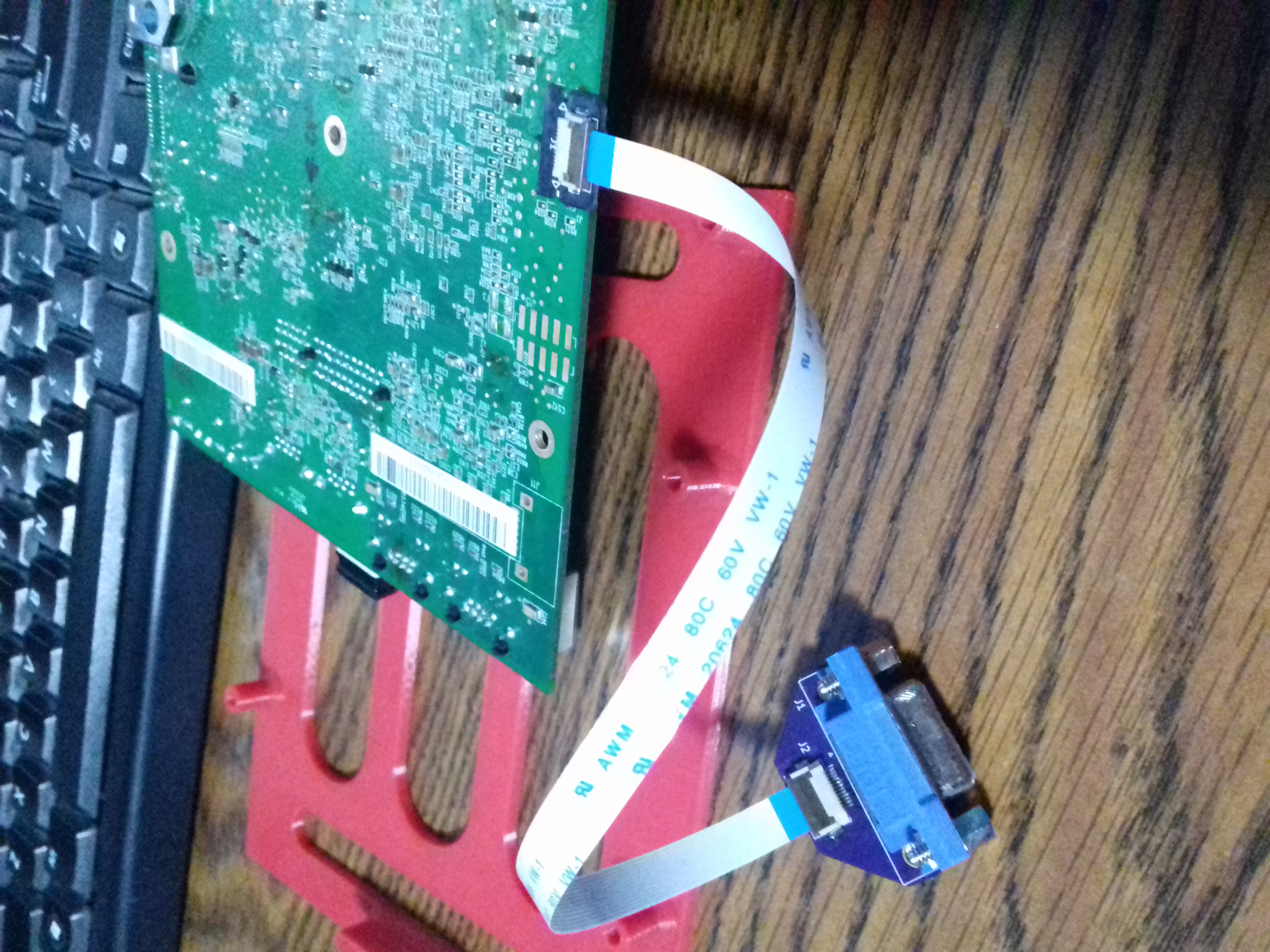
I’m currently assembling a combo PCB with 2x USB, USB-serial using the CH330, and VGA. It’s very handy. I’ve successfully tested out the USB-serial and VGA, and am currently waiting for a parts shipment to arrive from Digikey for the USB section. Attached a PDF of the schematic to sate your curiosity (on Imgur, as I’m a new user, so I can’t upload )
Ok so it appears my VGA output is wonky, only get Green. Checked with an O-scope and up red and blue appear to be toast and I get no signal on those pins. I had though about doing the custom CCA but now that I know it doesn’t work correctly it is not worth it. Hoping the SATA works waiting for a power cable so I can get 5v to a SSD. If not I guess I will have to re-think how I want to use this.
Additionally, here’s a picture showing the right-angle SMT header that WD uses on this board when this board is used on the RX4100 and Arkeia Network Backup device:
Depending on the exact board revision you have, the ESD protection circuitry may not actually be present. It tends to be there on -001 boards, but not so much on -003 boards.
For anyone who’s looking, I found a header that closely matches the one pictured above. Part number is 10112690-G03-06ULF, it’s made by Amphenol. You may be able to get a standard right-angle header in there as well but I’m not sure if there’s enough clearance between the board and the top of the unit to allow you to get the cover back on.
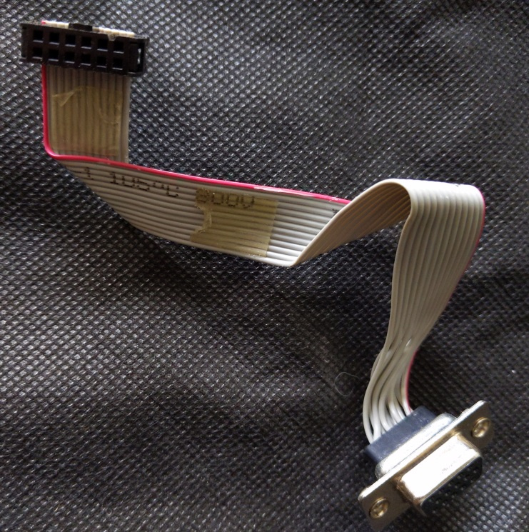
Don’t have a source on a cable yet but I would think (correct me if I’m wrong) the pinout is the same as the cables you occasionally find with video cards that have a cabled dsub port which you can find those all over ebay for cheap (still trying to find the pinout for those to be sure).
EDIT: Ordered the header above but found out it’s too small for the spot on the board. Thus far, the best/cleanest solution would be the one by MoltenSolderLabs
Most of the video card cables are using a 16 pin connector on the board end and the DX4000 needs a 12 pin connector. Even if you find an older cable with the requisite 12 pin connector, they have a different pinout. If you find a 12 pin cable that is using a soldertail VGA connector, you could rewire it to conform to what is needed here, but most of those cables are too short to reach the back panel of the DX4000.
The way I did it isn’t really…the best looking…but it is cheap and very quickly done (<15 minutes), no re-soldering custom pinouts necessary.
The J3 header is first coated with a very thin layer of solder, then the daughterboard (0.8mm thickness) is pasted on top of it using a hot air gun. Any excess solder flows out (as the bottom layer is masked, except for the contacts, and I didn’t put a ground plane to minimize the issue of shorting out).
You can find 0.5mm pitch forward-forward cables for $2 for a cable length of 25cm in 5 qty, and 12 pin 0.5mm SMT headers for $2 for 10 qty. Both PCBs combined are $5.60 with free shipping from OshPark (possibly can get it a bit cheaper from Chinese fabhouses). The VGA female connector is the most expensive, at $4.53. You could make the PCB even cheaper by replacing that high-density VGA female connector with a standard one (at the expense of slightly greater PCB cost). Total: <$15.
(The red, 3D printed part is a “test-bed” I made in order to be able to screw it in place and probe the DX4000 without worry of slipping a probe and shorting something out).
Frozen001, you can do some basic checks to see what might be wrong with the VGA outputs. With a meter set to ohms, you should see ~75 ohms to gnd on each of the R, G and B pads of J3. Additionally, you can measure continuity from each of the R, G and B pads of J3, to D10 pins 1, 3 and 6. See the picture below.
You can also see in the picture, traces going from D10 pin 1 to L24 and pin 6 to L25. These are the red and blue signals. Sometimes components like L24 and L25 can get damaged when handling the board. Check to make sure those components are in place and not damaged. Should be near zero resistance from one terminal to the other. You said the green was working, so we don’t need to check that one.
If you do see damage, you can simply short across the terminals of L24 or L25, since these are only ferrite beads and they don’t do much at video frequencies anyway.
Thanks for pointing me to that location. D10 was missing in may and it had a glob of solder across the pond. I removed the solder and the display is better, my cable is not the best, but I have a fix for that in the works. Now to figure out my the SSD I put on the 5th SATA port is not working correctly. It detect it is int BIOS but when I go to partition it, it fails.